
Model 3D is designed for 2x4 walls with downward venting exhaust systems and floor standing dryers.
Downward Venting

Installation Instructions
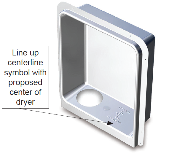
- All standard American clothes dryers have an exhaust port in the center of the
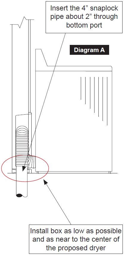
rear panel at the very bottom. Therefore, it is best to install Dryerbox® as low as
possible so that the bottom tab is at or slightly below the finished floor level (not applicable
if stackable unit or on a pedestal (Diagram A). The centerline mark on the
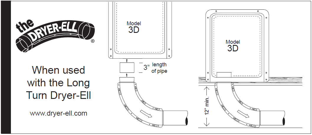
Dryerbox® should be located as close to the proposed appliance center as possible. - This model is for downward exhaust direction. If you are venting up, out or to the
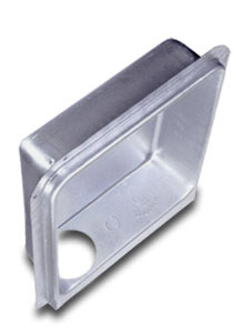
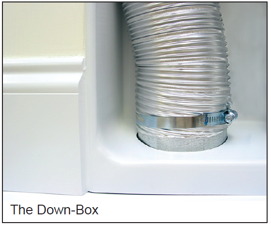
side use our original Dryerbox® Model 425 or 350. - Consider installing the 4 1/4” deep Down-Box (Model 4D) into a 2x6 wall for the
additional depth and location of the pipe penetration within the bottom plate. - When installing in an exterior frame wall, you should add insulation or duct board
to the back-side of box to minimize condensation and temperature transfer. - To achieve a fire resistance rating (one-hour F & T) min. 2X6 wood or metal framing
is required. The Dryerbox unit must be installed in accordance with the UL Cabinet
System listing. An extra layer of type-X drywall must be installed in the ID of the stud
cavity in which the Dryerbox is located. Drywall must be attached to nailers (minimum
1” X 2”) located on the inside of the cavity wall studs. Secure nailers to wall framing at
max 18 in. OC. The screws used to attach the inner layer of drywall shall be spaced a
maximum of 18 inches apart. For metal studs, mineral wool (min density 4 pcf) must
fill the entire Dryerbox wall cavity and minimum R13 Fiberglass insulation in adjacent
cells. For wood studs, mineral wool or R19 Fiberglass insulation must fill the Dryerbox
cavity. Visit www.dryerbox.com/firestop for more detail. - Gas line termination options: For black iron pipe, wrap vinyl tape around throat
where it penetrates. For corrugated stainless steel tubing, secure the CSST
Termination Fitting with a Jamb nut to securely affix the termination to the
receptacle. The gas port can be enlarged or relocated easily with a step bit. The
best location may be in the center on the bottom return. - Insert the 4” snaplock pipe about 2” through bottom port for the homeowner
to connect the flex transition hose at a later time (Diagram A). Secure with silver
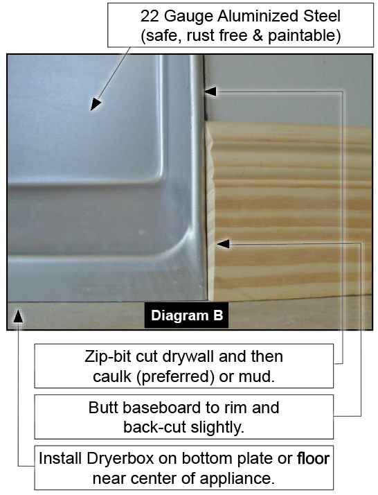
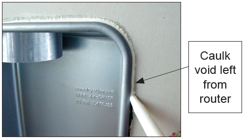
tape, foam or caulk. - Use a Roto-zip-bit router tool to cut the drywall leaving a caulk joint for the painter
(Diagram B). It is best to caulk or mud this void (required for One-Hour Rating). - The baseboard is best terminated with a tapered back-cut into the rim extension
on either side of box (Diagram B). - Exposed metal can be left unpainted or can be sprayed with an acrylic latex or oilbased
(alkyd) paint when the rest of the wall, trim or baseboard is painted..