


The 425 is the flagship model having been designed for the most common new construction dryer exhaust configuration. While there are a few exceptions, it is primarily used for venting upward in 2 X 6 walls. Where wall depth is restricted, it can be installed in a 2 X 4 wall with a 1" furring strip. The only time the 425 should be rotated is to support pedestal or stacked units for downward venting. This model was designed to allow room for other mechanical components in the cell of the wall. It is narrow enough to share plumbing or electrical runs.
To provide dryer-type flexibility (in the event that someone wishes to change from a pedestal dryer, for instance, to a floor standing dryer), select the new Model 480 for a standard installation.

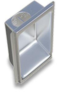
The Original Model
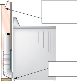 Diagram A
Installation Instructions
- All standard American clothes dryers have an exhaust port in the center of the rear
panel at the very bottom. Therefore, it is best to install the Dryerbox® as low as possible
so that the bottom tab is at or slightly below the finished floor level (Diagram
A)—not applicable if stackable unit or on a pedestal. - Attach Dryerbox® to stud and bottom plate at a minimum of 3 corners.
- This Dryerbox is designed to accommodate an upward exhaust direction. Optionally
this unit can be mounted in a downward exhaust direction for a stacked dryer
or one on a 13 inch pedestal. A lying-on-its-side orientation is also an option. For
floor standing dryers venting down, the Model 4D or 3D are recommended. - When installing the 4 ¼” deep Dryerbox® (Model 425) into a 2x4 wall, fir out the
respective wall ¾” with a 1x2 furring strip to provide adequate depth or use the
3 ½” Model 350. - When installing in an exterior frame wall, you should add insulation or duct board to
the back-side of the box to minimize condensation and temperature transfer. - To achieve a fire resistance rating (one-hour F & T) min. 2X6 wood or metal framing
is required. The Dryerbox unit must be installed in accordance with the UL Cabinet
System listing. An extra layer of type-X drywall must be installed in the ID of the stud
cavity in which the Dryerbox is located. Drywall must be attached to nailers (minimum
1” X 2”) located on the inside of the cavity wall studs. Secure nailers to wall framing
at max 18 in. OC. The screws used to attach the inner layer of drywall shall be
spaced a maximum of 18 inches apart. For metal studs, mineral wool (min density 4
pcf) must fill the entire Dryerbox wall cavity and minimum R13 Fiberglass insulation
in adjacent cells. For wood studs, mineral wool or R19 Fiberglass insulation must fill
the Dryerbox cavity. Visit www.dryerbox.com/firestop for more detail. - Gas line termination options: For black iron pipe, wrap vinyl tape around throat where
it penetrates. For corrugated stainless steel tubing, secure the CSST Termination
Fitting with a Jamb nut to securely affix the termination to the receptacle. The gas
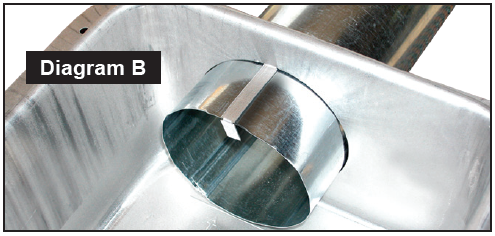
port can be enlarged or relocated easily with a step bit. - The new Duct Support Tab (Diagram B) in top port will assist in maintaining the ideal
penetration length of the 4” Snaplock rigid conduit of 2 inches. Create a “hook” by
bending the tab at the weakened or scored locations. Break-away when duct is fully
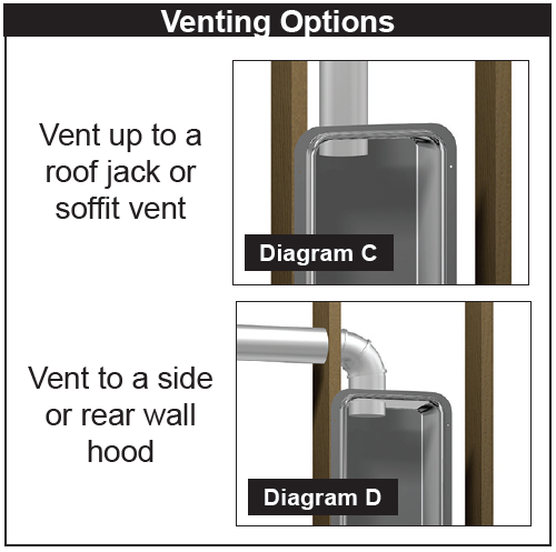
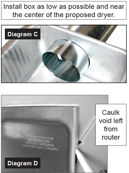
supported in-place. Seal penetration with foil tape or sealant caulk. - Snaplock pipe can be vented up (Diagram C) to a roof jack (see dryerjack.com), to a
side-wall vent hood (Diagram D) or downwards to a crawl space or floor joist system
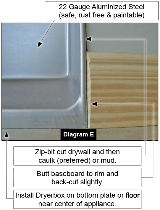
with two elbows. Use the Model 4D or 3D to go down. - Use a Roto-zip-bit router tool to cut the drywall leaving a caulk joint for the painter
(Diagram E). It is best to caulk or mud this void (required for One-Hour Rating). - The baseboard is best terminated with a tapered back-cut into the rim extension on
either side of box (Diagram E). - Exposed metal can be left unpainted or can be sprayed with an acrylic latex or oilbased
(alkyd) paint when the rest of the wall, trim or baseboard is painted.
When installing The Dryerbox in a 2x6 wall, the model 425 is an excellent choice! This sleek model is narrow enough to allow room for plumbing and electrical to run alongside. Even within a 2x4 wall, it can be installed with a 1 inch furring strip. Designed to be used for upward venting, it can also be rotated to support pedestal or stacked units to accommodate downward venting.
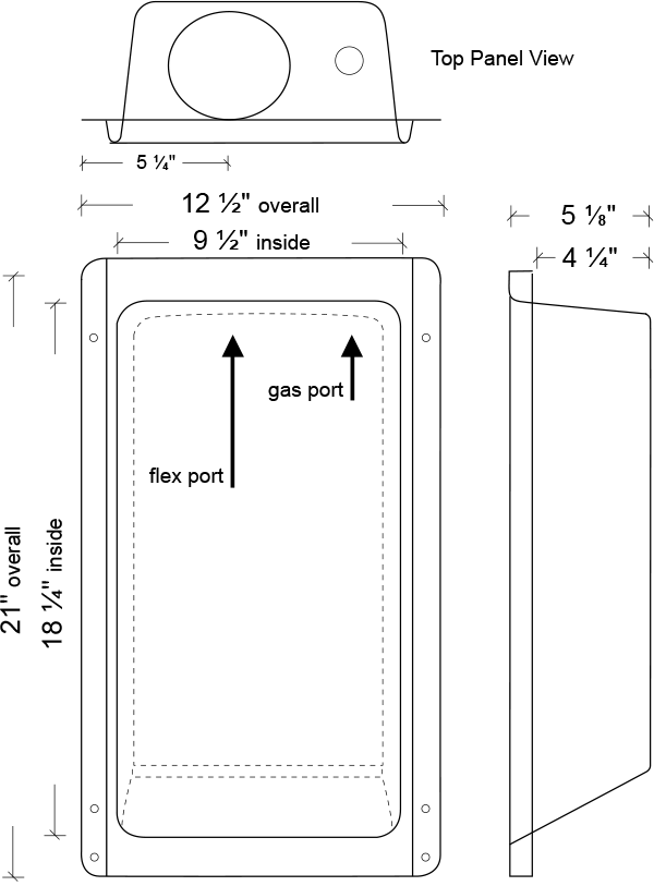
The Dryerbox model 425 is made of 22 gauge aluminized steel, weighing 4.14 pounds. The distance from the nailing flange to the rear of box is 4 1/4", and the overall measurements are 21" h x 12 1/2" w x 5 1/8" deep. The inside measures 9 1/2" wide x 18 1/4" tall.